Following on from this thread I thought I´d post up a step by step guide to making one. This one uses 15 amp cable and is protected by a 15 amp fuse so will be ok to use for supplying up to 180 watts of power for your accessories. This box will have 3 connection points inside, but you can put in as many or few as you like.
Before I start though, here´s the disclaimer - I´ve made these before for myself and they´ve worked. However, if you do follow these instructions and you electrocute yourself, set fire to your bike or blow up someone´s granny don´t come crying to me because I´ll just :laugh: Make use of the sketch in the above mentioned post to make sure I have the relay connections correct, take your time and be careful.
You´ll need the following items: a 30 or 40 amp SPNO (Single Pole Normally Off) relay, 15 amp cable (preferably two different colours - one for "live" & one for "earth", 15 amps screw terminals, an inline fuse holder and fuse, some 6.35mm crimp terminals and a box to put it all in. You´ll also need wire strippers/crimpers, a pair of pliers, a drill & a couple of bits, some epoxy resin (or other glue) and a couple of small screwdrivers.
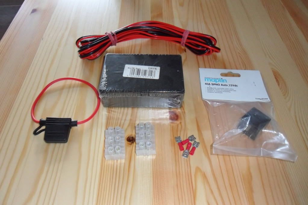
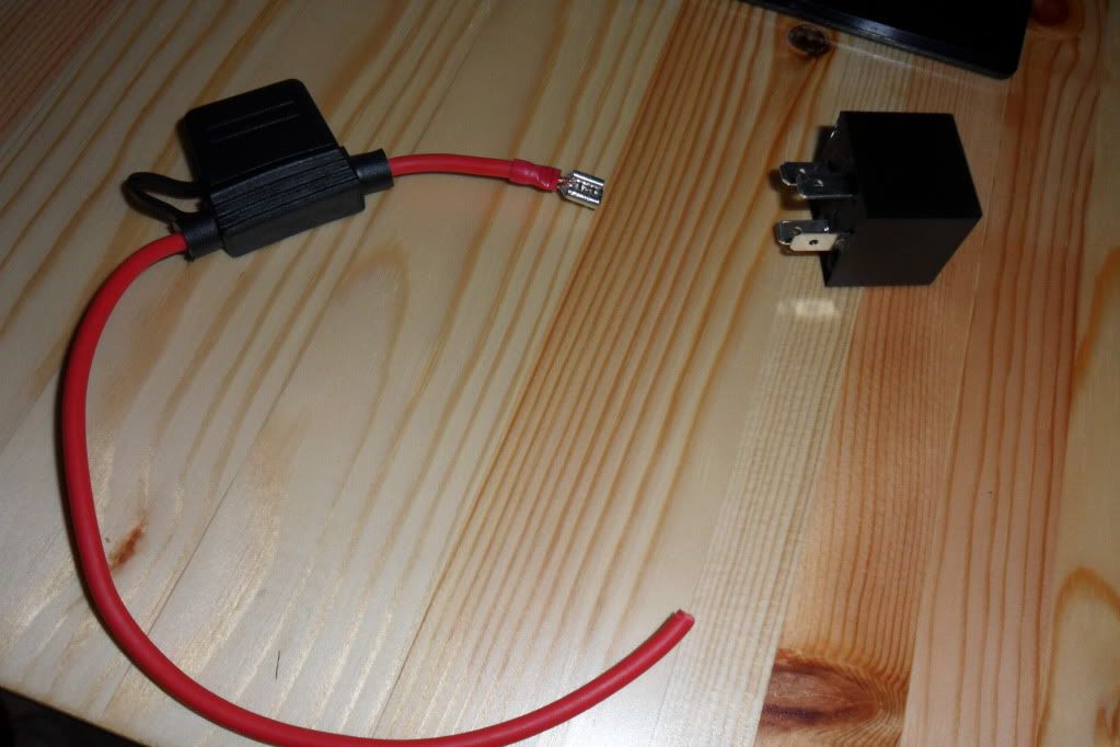
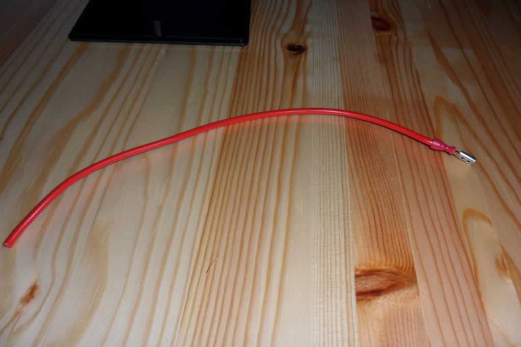
If your relay has a metal fixing bracket, you can remove it as it´s not necessary. Put a 15 amp fuse in the fuse holder, strip the insulation off one end of the wire and crimp on one of the terminals.
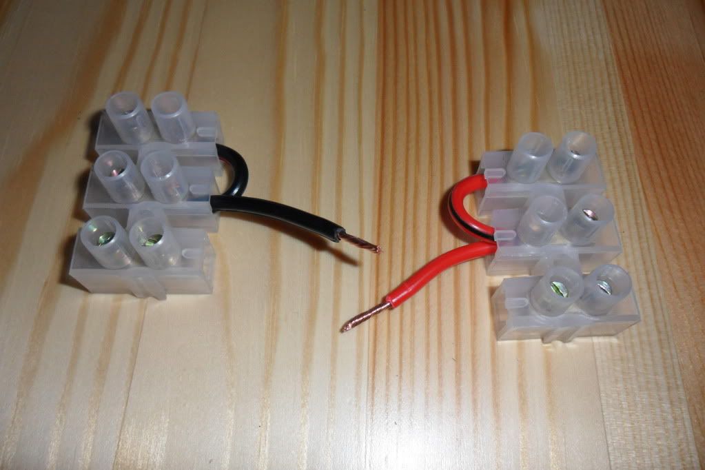
Cut two short lengths of each colour cable (approx. 50mm long) & strip the ends.
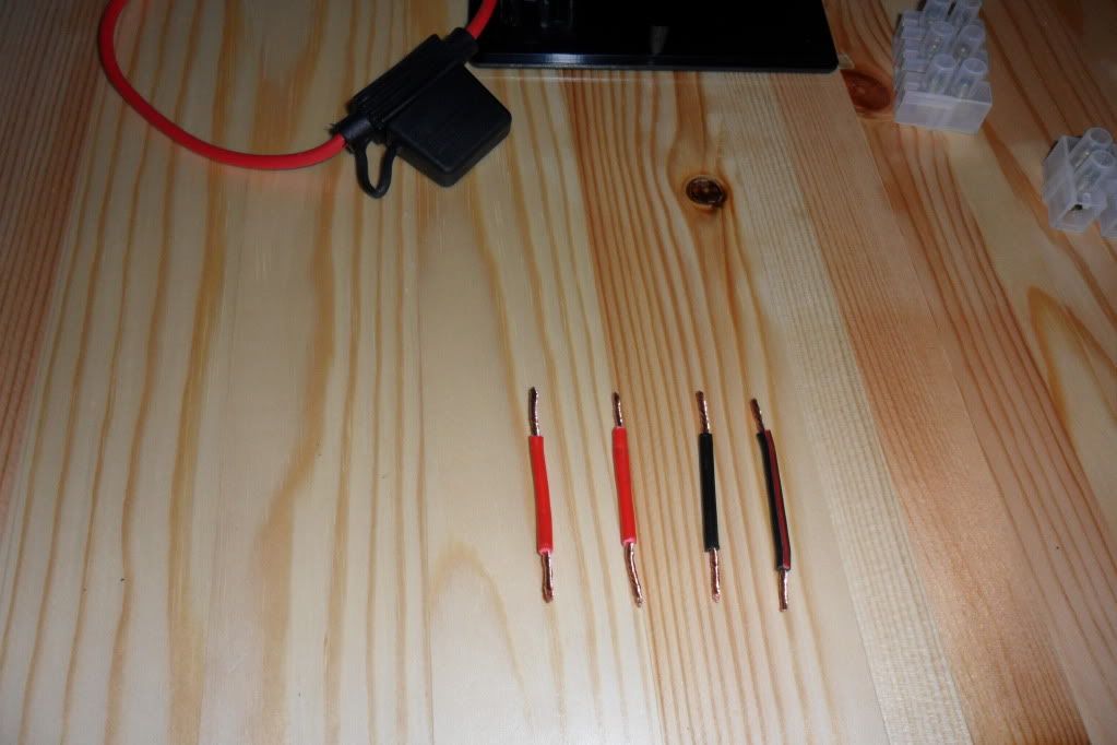
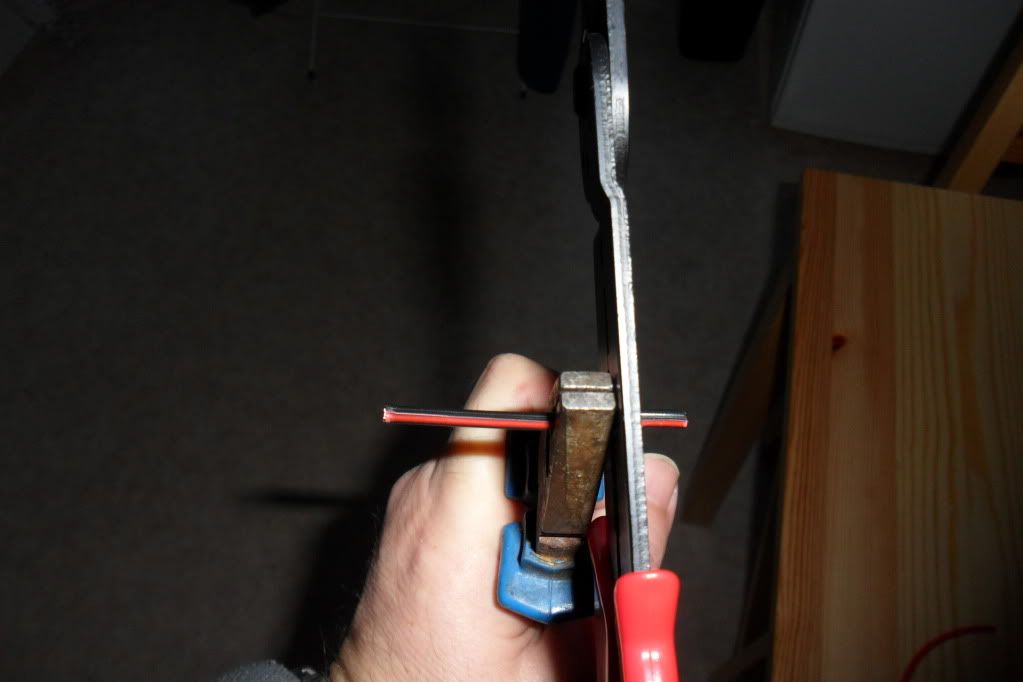
Here´s a tip - when stripping short lengths of cable, hold the cable with a pair of pliers instead of your fingers. This will stop the copper wires being pulled completely out of the insulation.
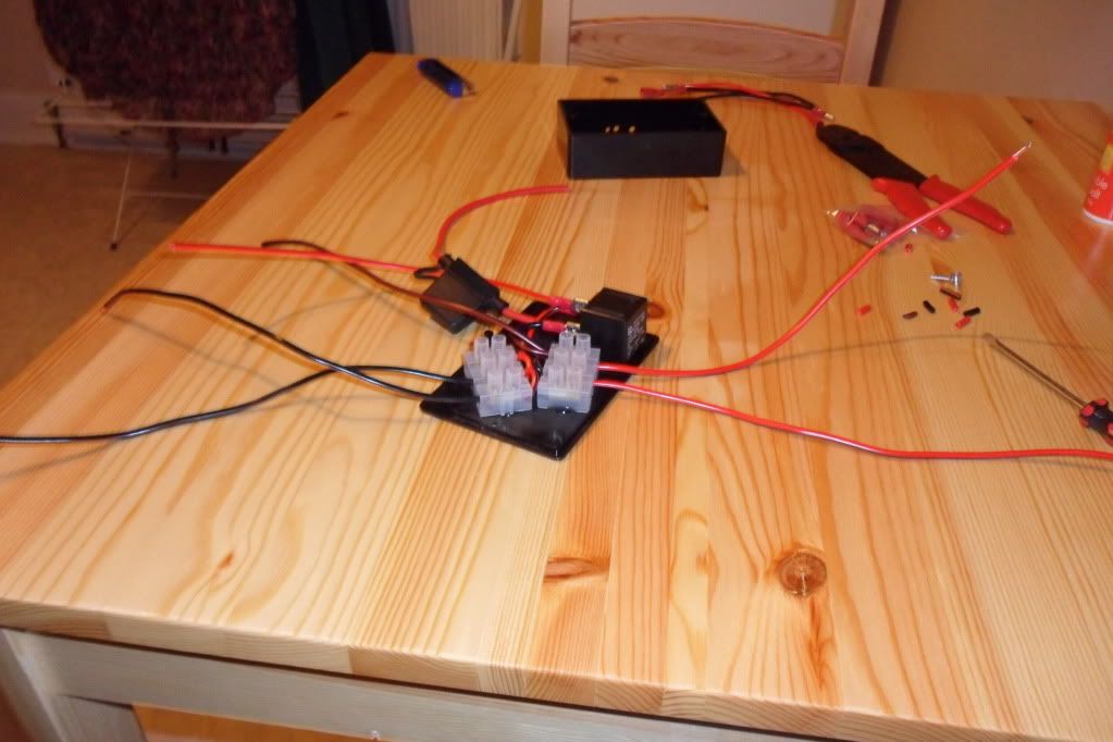
Connect these short cables to the screw connectors as shown. When you´ve tightened the screws give each cable a little pull to make sure it´s secure in the connector.
Cut another length of each coloured cable, approx. 75-100mm long depending upon the size of your box, strip the ends and fit a crimp terminal to one end of each.
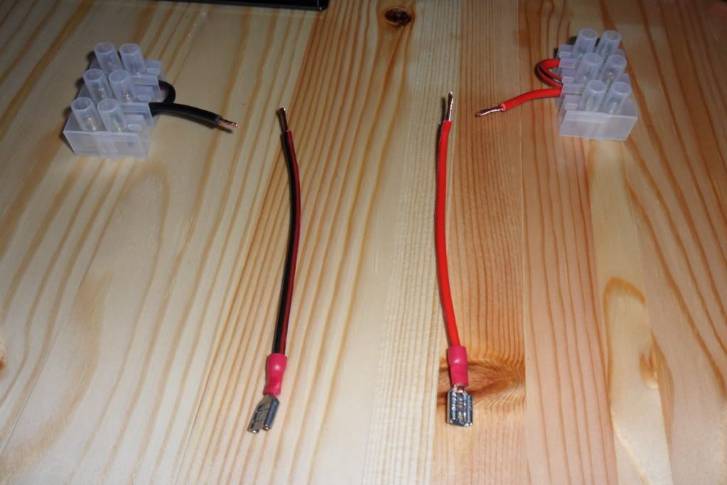
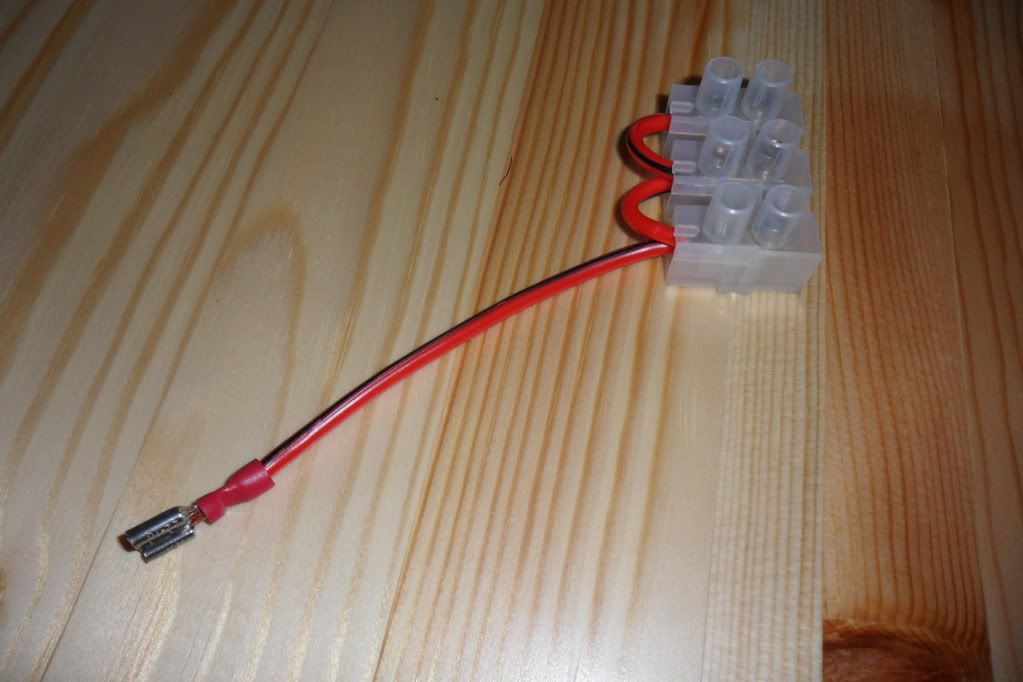
Connect the "live" cable to the connector as shown below. This longer cable connects up to the relay later.
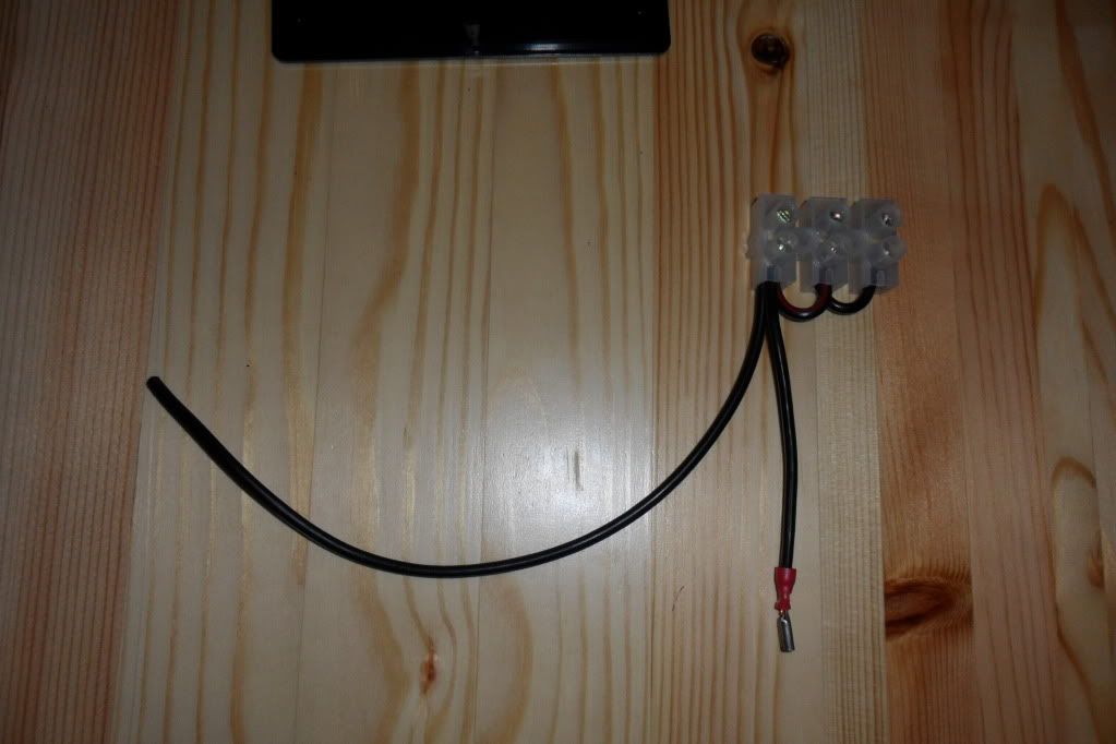
Cut another length of "earth" cable, approx. 300mm long, strip one end only and connect your two "earth" cables to the connector block as shown below. This long "earth" cable will be used to connect to the bike battery.
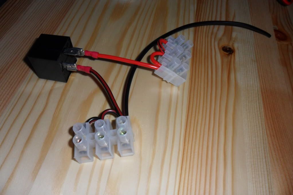
Connect the crimp terminal from your "live" connector block to terminal 30 on your relay. Connect the crimp terminal from your "earth" connector block to terminal 86 on your relay.
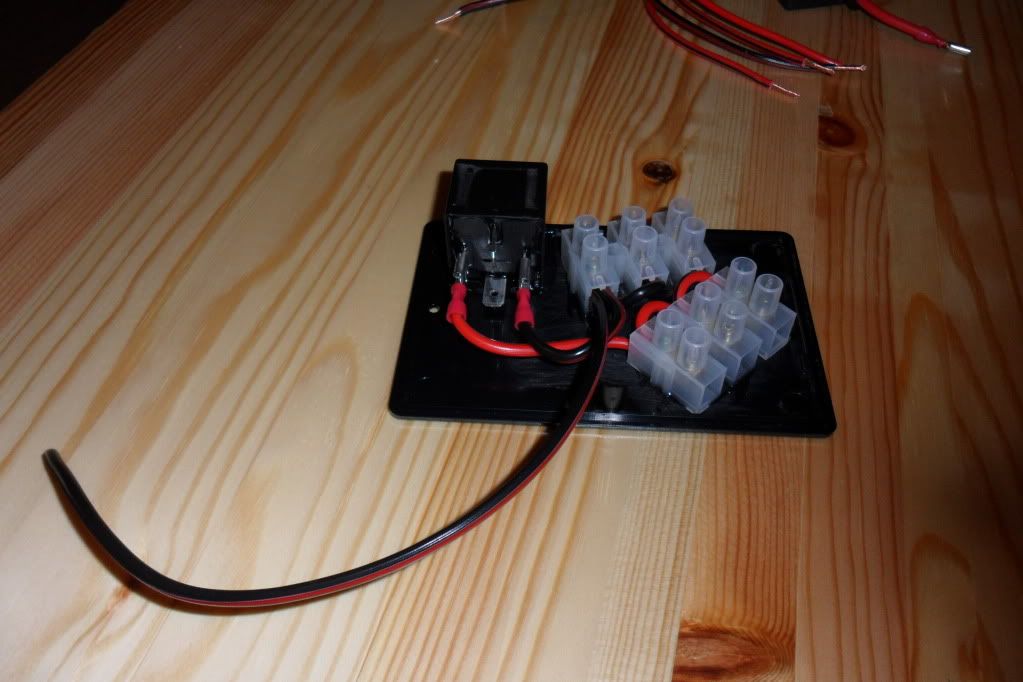
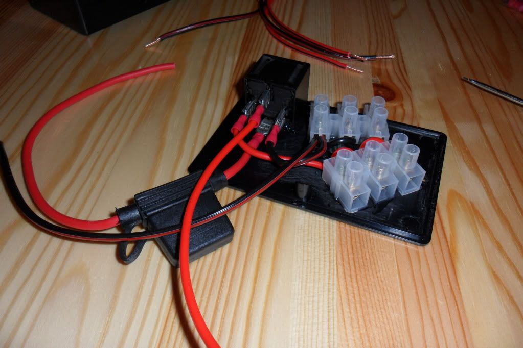
Now, using the epoxy resin (or other glue), glue the relay and connector blocks to the inside of the lid of your box. A bigger box would´ve made this easier for me, so I had to glue the connector blocks on an angle to make sure everything would fit in. Remember to make sure you don´t block the screw holes in the lid of your box. You may need to put something heavy on top of the relay/blocks, or clamp them, to hold them still till the glue sets as the cables tend to move them around. Another tip - rough up the box lid and side of the relay with sandpaper. This gives a better surface for the glue to stick to.
While you´re waiting for the glue to set, cut some "flying leads" to connect to your accessories and strip the ends.
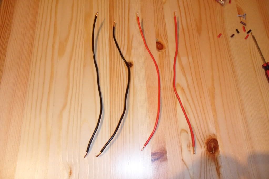
Cut a length of "live" wire, approx. 300mm long, and fit a crimp terminal to one end.
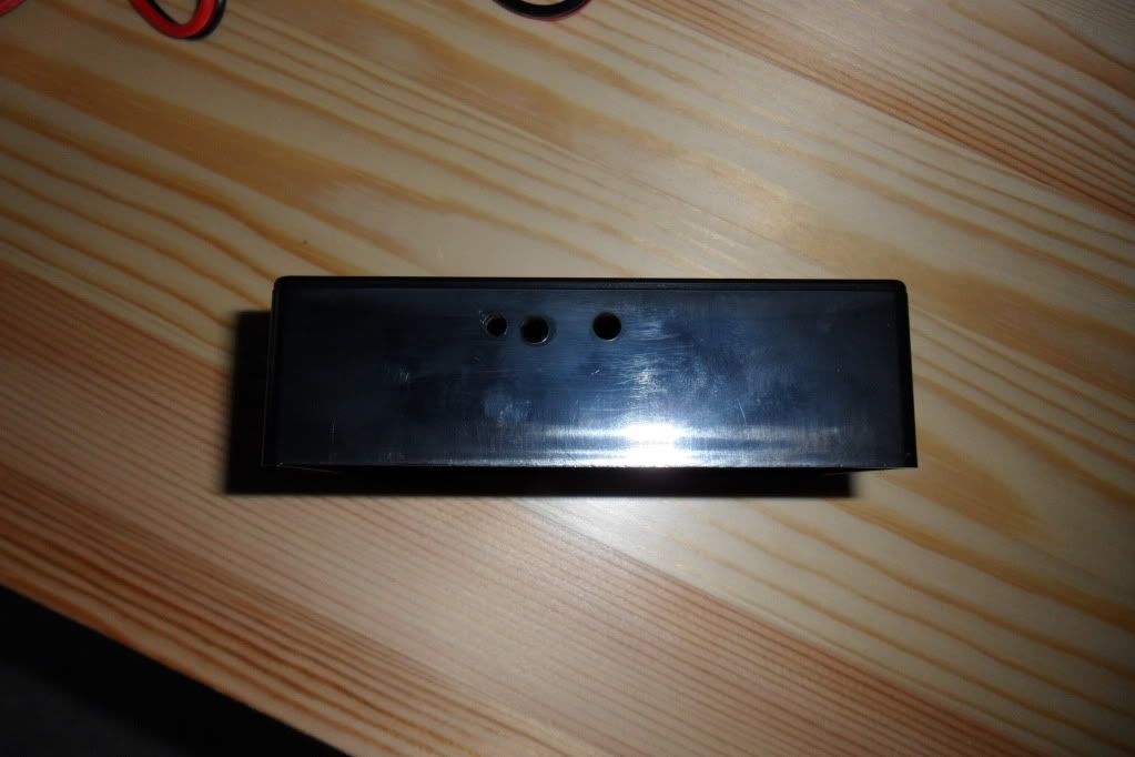
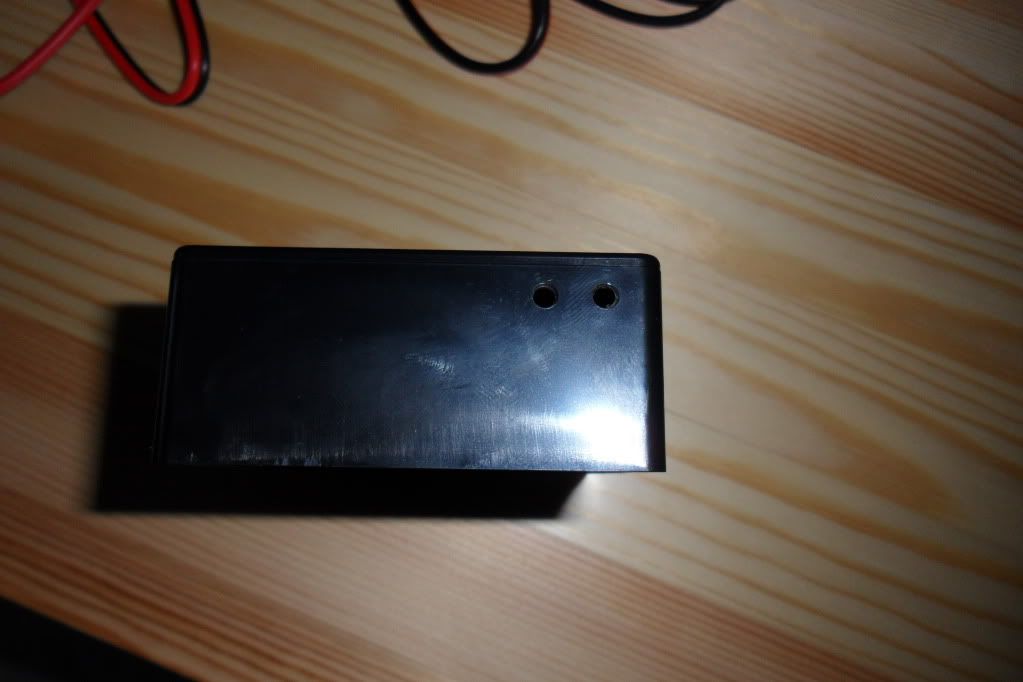
You can also drill some holes for the various wires to exit the box. I drilled 3 holes in the side for the battery/trigger wires and 2 holes in each end for the accessory wires.
Once the glue has set, connect the crimp on the fuse holder to terminal 87 on the relay. Take the 300mm long cable you cut earlier then fit it to terminal 85 on the relay.
Now connect the "flying leads" you cut earlier and connect them to the connector blocks, live to live & earth to earth.
Now the fun starts - it´s time to feed all these cables through the holes you drilled in the box.
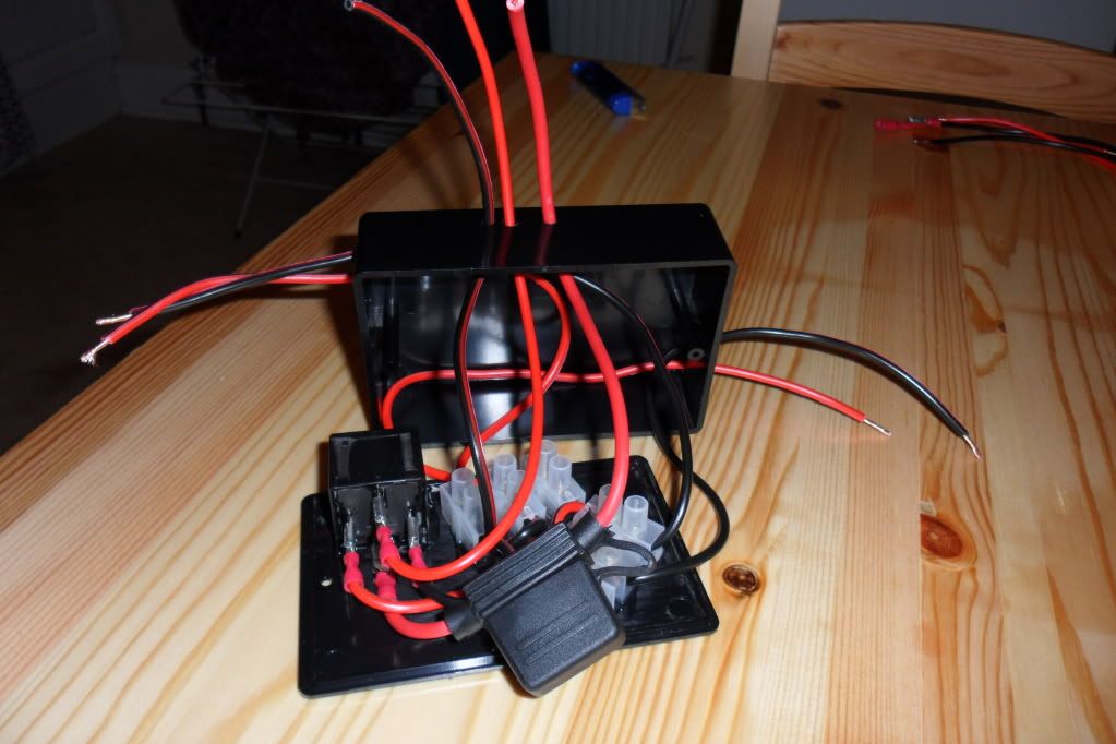
Pull the slack through the holes on all the wires, leaving some still inside the box. Tuck everything inside as you close the box onto the lid.
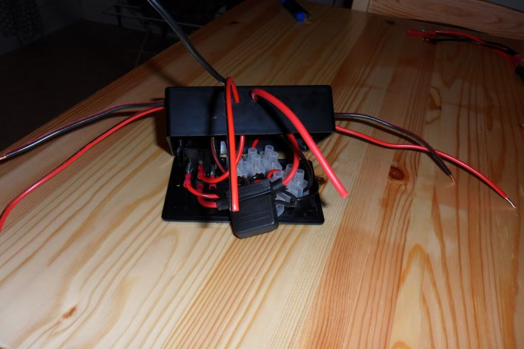
Once everything is inside the box secure the lid with the screws provided.
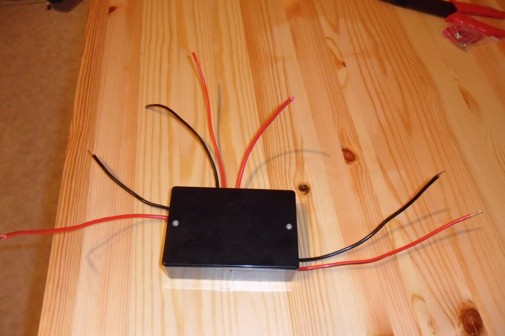
Trim all the "flying leads" to the length you require, then crimp some connectors on the ends of all the cables. For safety use female connectors on the "live" wires & male connectors on the "earth" wires (thanks Mad Cow!).
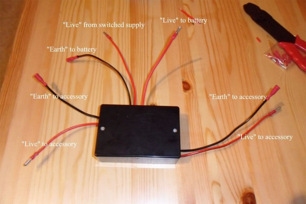
And that´s it, your box is finished! All that´s now required is to make some leads to fit onto the "flying leads" from your box and connect them to the battery, a switched supply (e.g. brake light circuit) and your accessories. I do it this way, using "flying leads", as it makes it easy to disconnect the box if you even need to without having to disconnect wires from the battery, etc.
One other point to add - you only need to add your accessory "flying leads" as you need them; I´ve done two in the above as one will be for my Autocom under the seat, the other will be for a 12v socket I´ll be mounting in the dash.
I´ll be fitting this one to my bike at the weekend so I´ll take some pics showing the connections.
Have fun!
How to - Make your accessory relay box
- knobblywobbly
- Posts: 292
- Joined: Sun Feb 13, 2011 10:56 am
- Been thanked: 5 times
Re: How to - Make your accessory relay box
One potential danger I can see with your set up is the use of male connectors on the red flying leads. As these are live when the relay is switched they could touch the frame and short out.
You should always fit live leads with a female insulated connector to prevent this. Fit male connectors to the earth leads by all means as it doesn't matter if these touch the (earthed) frame.
Think of a male connector as a plug and female as a socket, so just like with household electricty, the live side goes to the enclosed (female) sockets, whereas the accessory always has an exposed (male) plug as it contains no electricity when the contacts are exposed. As soon as it is connected (plugged in) the contacts are hidden and insulated.
Always stick to this principle and your electrickery will be much safer!
-
- Posts: 521
- Joined: Thu Oct 27, 2011 10:19 am
Re: How to - Make your accessory relay box
Hi ya
Nice article, well explained. I agree with Mad Cow about exposed live wires, however you still get my vote for best "How To" so far.
Ian
Nice article, well explained. I agree with Mad Cow about exposed live wires, however you still get my vote for best "How To" so far.
Ian
The Geek shall inherit the Earth.
-
- Posts: 1514
- Joined: Mon May 09, 2011 7:28 pm
- Location: Stourbridge
- Has thanked: 207 times
- Been thanked: 92 times
Re: How to - Make your accessory relay box
A very useful how to.
My only comment would be to add grommets to the drilled holes to prevent chafing.
The lightest piece of kit is the one you leave behind...
Re: How to - Make your accessory relay box
I should have said that apart from my comment above, as very nice neat solution.
I have a similar set up but use one of these:
Available from [url=hhttp://www.vehicle-wiring-products.eu/VWP-onli ... php#boxttp://]Vehicle Wiring Products[/url]
On my Tiger I have a relay that has a built in fuse (so no need for one between battery and relay) the power to accessories is then looped back to the three fuse slots so all are independantly fused. I currently use this to power a Stebel Magnum horn and a 12v accessory socket on the bike, with a spare feed.
-
- Posts: 1464
- Joined: Sun Aug 08, 2010 4:41 pm
- Been thanked: 2 times
Re: How to - Make your accessory relay box
Good guide KW! As well as Maplin which has been mentioned, another great source for auto electrical parts are http://uk.rs-online.com/web/ and also any Marine stores which have ready made waterproof components.
cheers Marc
cheers Marc
Too many Cagiva Elefants, Gran Canyons and Ducatis!
Azzalin SP and various others.
- knobblywobbly
- Posts: 292
- Joined: Sun Feb 13, 2011 10:56 am
- Been thanked: 5 times
Re: How to - Make your accessory relay box
Good point regarding the male/female connectors Mad Cow - "How To" duly updated.
Re: How to - Make your accessory relay box
That was brilliant post I'm gonna have a go at that,
Thanks for the effort
Re: How to - Make your accessory relay box
A timely post too. I was just thinking that I ought to do one for the fazer as I keep buying farkles for it. Thanks.
The secret of a long life is knowing when its time to go.